![[0x0v1]](https://www.0x0v1.com/content/images/2023/09/0x0v1-1.png)


Introduction
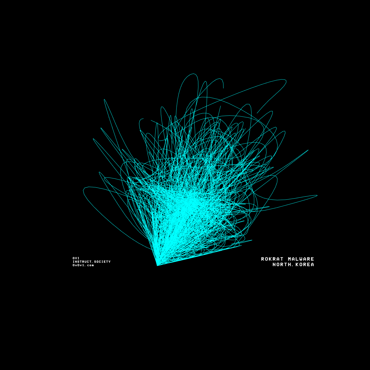
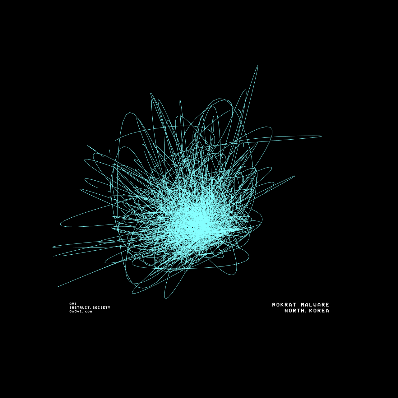
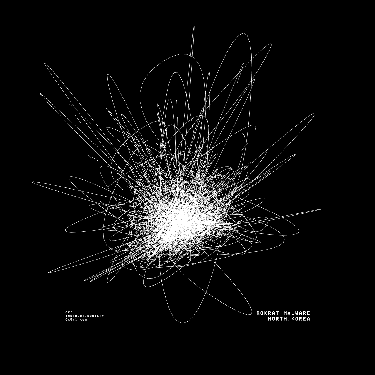
This is a paid subscriber only tutorial that gives you exclusive access to learn how I created the programmatic visualizations of malware within the instructSOCIETY project and on the gallery page seen here.
It will show you how I am programmatically manipulating 3D images to create artistic representations of the malware like what is in the video above and shown below. At the end of the tutorial, I have made my Project Files available for download, so you can plug and play your own models.
In order to produce these models & visuals, I am using TouchDesigner as my modelling engine. In the free tutorial I released here, I was using Blender to create a static 3D model. In this situation, I want a model that can be manipulated in real time & program it to respond to action.
TouchDesigner is free & is widely used in the fields of digital art, stage production, interactive installations etc. Its combination of real-time capabilities, flexibility, and extensive multimedia support makes it a powerful tool for us to create dynamic and engaging visual experiences using malware.
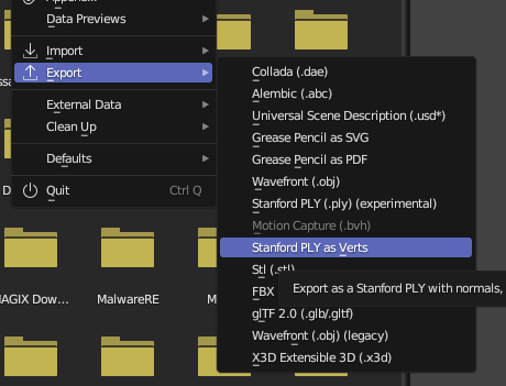
By following the previous tutorial, you should be at a point where you are able to have a 3D model in Blender. Once you have this, you can export the model to a PLY file. You can also use the instructSOCIETY_VizTool, which when run will output a PLY file. The only aspect of this you need to consider is that the PLY file needs a colour, otherwise once loaded in TouchDesigner, it won't appear.
Once you've loaded TouchDesigner, delete the template and start with a blank canvas. I recommend if you haven't used the tool before to familiarize yourself with how to programmatically manipulate data using their operators. There's plenty of resources online to do this, but I recommend having this cheat sheet file to hand - it helped me a lot. Nevertheless, I'll give a quick rundown of the operators TouchDesigner uses:
1. COMP (Component Operators)
Component operators are used to encapsulate and organize networks of other operators. They act as containers that can hold other operators, including other COMPs. This hierarchical structure allows for modular design and reusable components.
- Example:
Base COMP,Geometry COMP,Panel COMP,Camera COMP - Use Case: Organizing complex networks, creating user interfaces, managing 3D scenes
2. TOP (Texture Operators)
Texture operators handle 2D/3D data (textures). They are used for image processing, generating textures, and manipulating images in various ways. TOPs are often used for effects, compositing, and video processing.
- Example:
Movie File In TOP,Blur TOP,Level TOP,Composite TOP - Use Case: Applying filters to images, creating visual effects, processing video feeds
3. SOP (Surface Operators)
Surface operators are used to create and manipulate 3D geometry. They handle tasks like modeling, transforming, and deforming 3D objects.
- Example:
Box SOP,Sphere SOP,Transform SOP,Merge SOP - Use Case: Building and manipulating 3D models, creating procedural geometry, generating particles
4. CHOP (Channel Operators)
Channel operators process channel data, which is typically used for animation, control signals, and audio processing. CHOPs are essential for handling time-based data and driving animations.
- Example:
Constant CHOP,Wave CHOP,LFO CHOP,Audio File In CHOP - Use Case: Animating parameters, processing audio signals, controlling interactive elements
5. DAT (Data Operators)
Data operators handle textual and tabular data. They are used for managing data tables, scripting, and handling JSON or XML data.
- Example:
Table DAT,Script DAT,JSON DAT,Execute DAT - Use Case: Managing datasets, scripting logic, handling configuration files
6. MAT (Material Operators)
Material operators define the appearance of 3D geometry. They are used to create and apply materials and shaders to 3D objects.
- Example:
Phong MAT,PBR MAT,Constant MAT - Use Case: Applying textures and shaders to 3D models, defining surface properties like color and reflectivity
Before we get started in the demo, it's going to be most helpful for you to download the project files that I created and follow along, so you know what's going on. You can also just completely disregard the tutorial section and just play around with the project to see how it's working. I recommend doing this anyways, playing with the settings in each of the routines & operations can help you understand how to manipulate models in ways you wish.
Download the project files
Project walk through
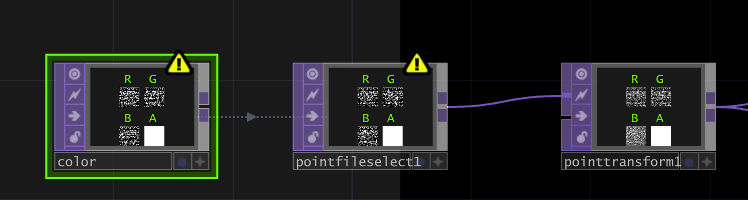
First we want to connect a few TOP operators to build out point cloud. This is used to establish our model data. We're going to first create a PointFileIn TOP (I've named this color), connected to a PointFileSelect TOP & a PointTransform TOP.
In the Point File In TOP's point data, we will load in our PLY file & set the Red, Green, Blue to our X, Y, Z coordinates. We set the alpha to Active.
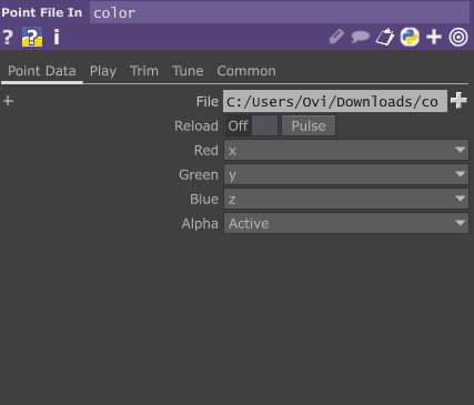
Select the PointFileSelect TOP & drag the PointFileIn to the PointFileSelect's
"Point File In TOP" field. From here, set the RGB to XYZ again.
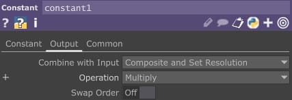
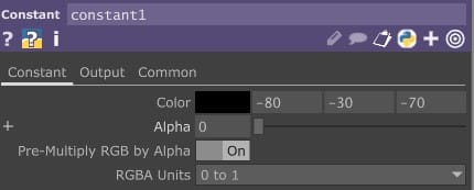
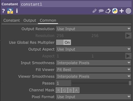
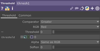
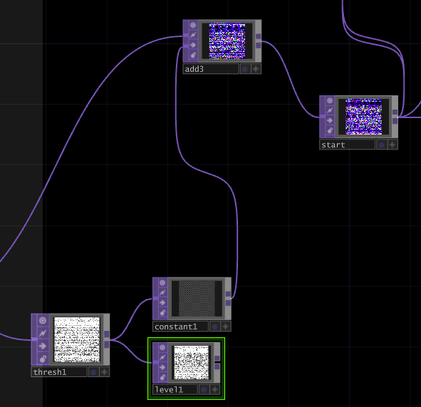
I then create this operation. I use a Points Transform Operator to customize how I wish to transform the points cloud. You can customize this how you wish. I then use a Threshold & a constant with a level TOP to add effect. I've shown my settings below, but remember this is all customizable for you - throughout the tutorial, I don't think it's necessary to demonstrate all settings, since you will figure it out as you go along.
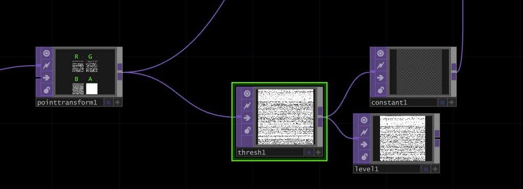
Once you created this operation, connect the Points Transform TOP & the constant TOP to a Add & then to a null (which I've named start). This then is used to begin our model visualization & manipulation.
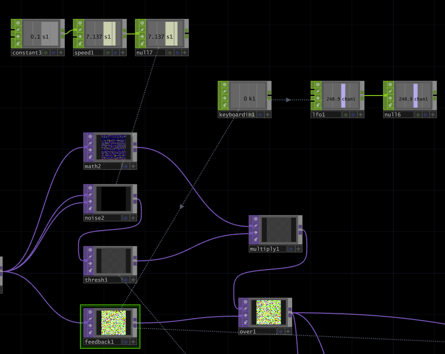
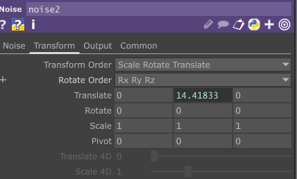
In the next routine, we want to join our null TOP to the following, making sure to drag in a keyboard CHOP to our feedback TOP. Our keyboard chop will join to an LFO & a null, and this will be used to reset our model to it's base position every time we want it by pressing 1. We also want to create a constant CHOP set to 0.1, joined to a speed CHOP with it's Order set to First. Finishing this routine with a null and linking this to the translate of our noise TOP. This will allow the model to rotate. The threshold TOP is set with a Greator comparator. Though this doesn't matter too much since our model has little colour. The rest of the operations here can be configured how you wish, but be sure to end the routine with a Over TOP.
(Linking any CHOP -> TOP etc is the same as what was demonstrated above).
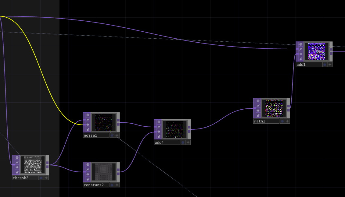
In the next routine, we wish to further manipulate the model by joining our Over TOP to a Noise & Threshold. We're using the noise TOP here to pull our particles back down in the model when they move upward. The threshold can be used to manipulate the RGB particles. This can give you different positioning effects like that shown below in the following GIF. In my model I've preferred to keep the structure as one piece. The Add, Math and Add connections are fairly self explanatory. Since the Adds allow for manipulation of the particles & the math controls the structure. Some manipulations you can see below with playing with Add & Math parameters.
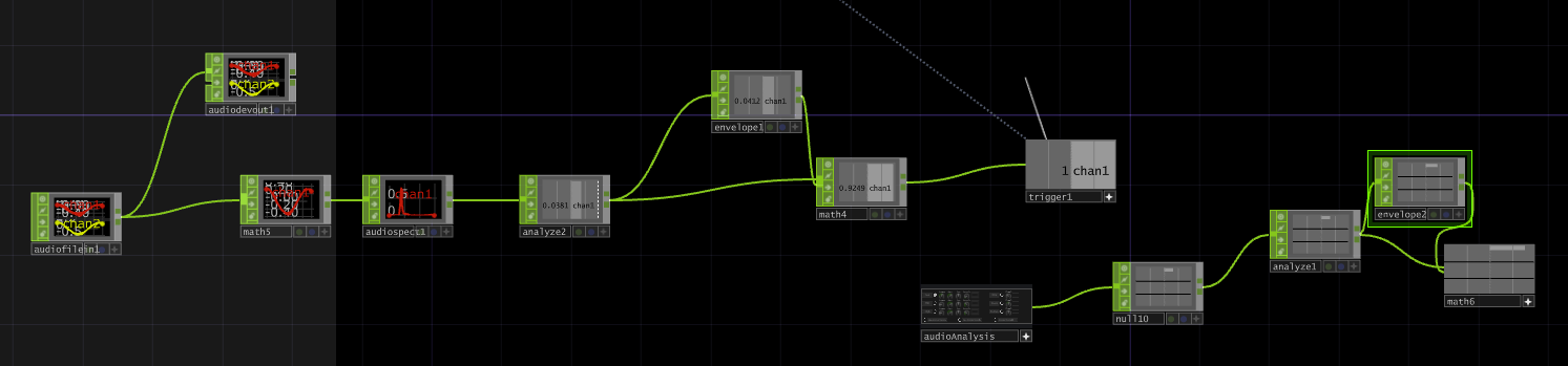
You will see the audio input routine that allows me to load in a audio file. Here I'm simply using a Analyze to monitor the kick, with an envelop & a math to increase the numeric value & then joining a trigger which is linked to my Noise TOP to create a drum kick pulse. There's also the option of using the audioAnalysis tool, so play around with that if you wish.
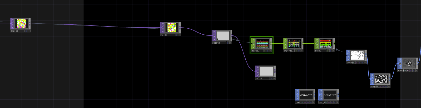
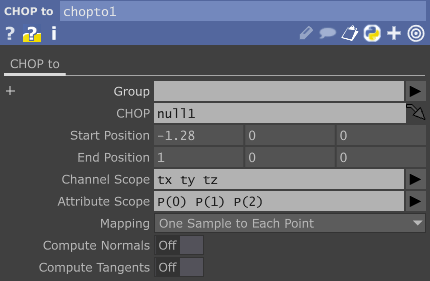
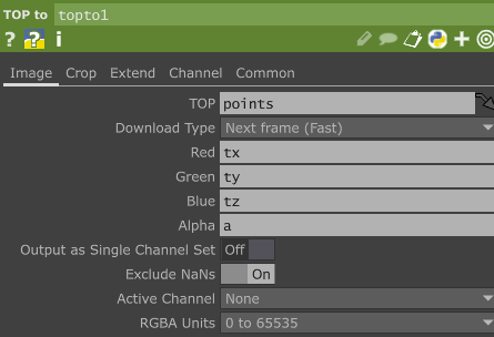
Next up we simply wish to start visualizing our model. You will see I've created the followning routine, which sends a limit to a null. This null is joined back to our feedback1 TOP to allow for the resetting of our model. I've then joint this to another null called points, which is sent to a toptoCHOP. This is joined to a shuffle & a null. Once you do this, it allows you to plot the points, visualize them & link the null to a chopto & a merge. We're now ready to build our camera system. You'll see that I've in fact used a convert SOP, were you can convert the model to NURBS Curves which will give you differing visual effects, play around with that as you wish.
Now, to get our camera set up, we simply need to connect our CHOP to a Geo. This Geo has standard settings with slight modifications to scale. Modify this as you wish. We then ad a camera for the Geo, a light to control the lighting of the enviornment & a ramp, null, environment routine to control the colour. These all point to a render, which will render our image. I've then used two adds to additional control, but they don't really do much for this tutorial. I use a transform to manipulate scale and pivots which finally points to a null & a movie out file where I can record the model.
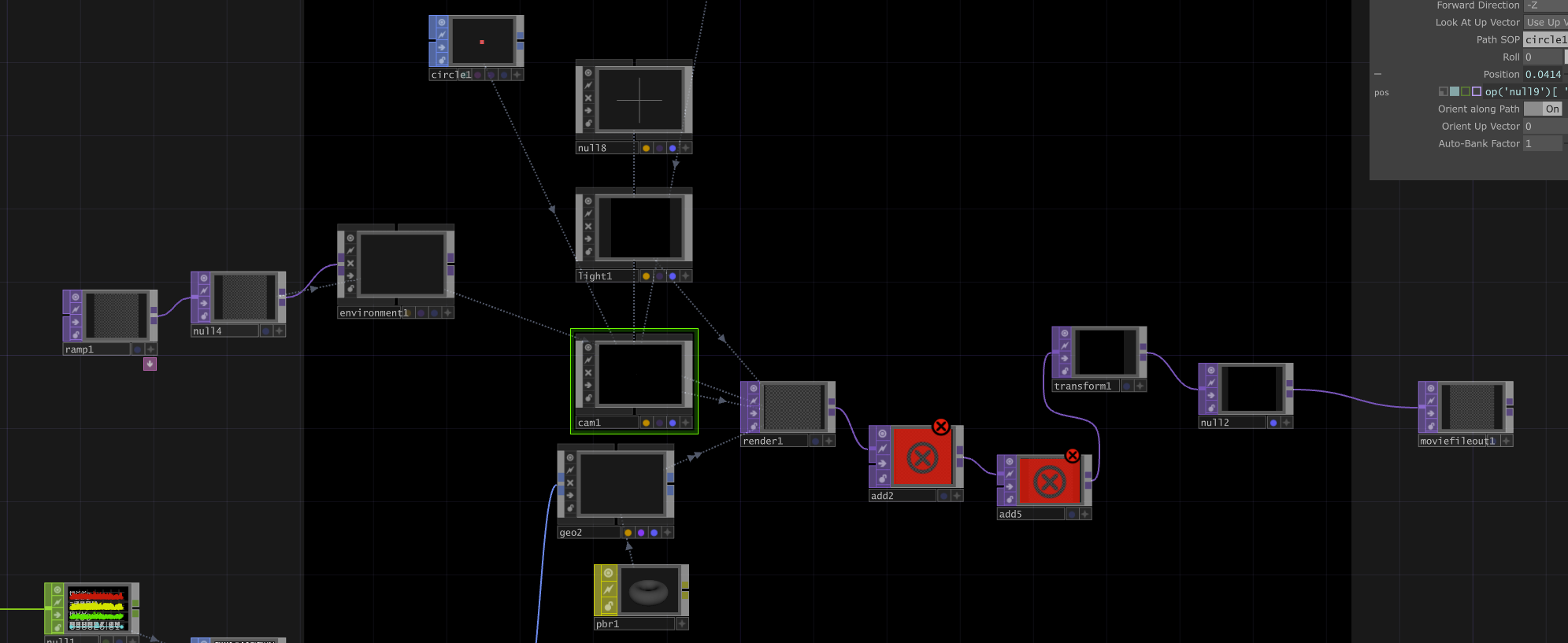
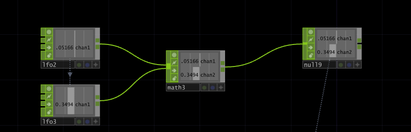
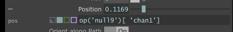
The most intricate part here is the LFO ramp, which is linked to the frequency channel of a Sine LFO. These then join to a math, which then rotate through a plus and minus digit. This is then linked to the position on our camera, which will control the rotation of the model.
Once we hit record on the Movie Out TOP we are able to modulate and control the model for recording, like shown below. And there, we've used TouchDesigner to visualise malware data and manipulate it.
Up next
In the next lot of tutorials, I'm going to be exploring visualizing malware at runtime, by building a system to experimental art visualization based on the register values of a running executable within an emulator. By capturing the state of the CPU registers at various points during execution, we can transform the data of malware at runtime into visually engaging.